
Vertical flow
Total material protection.

HEPA H14 filtration
Contamination reduced to a minimum.

Class A ISO 5
Certified safe under all operating conditions.
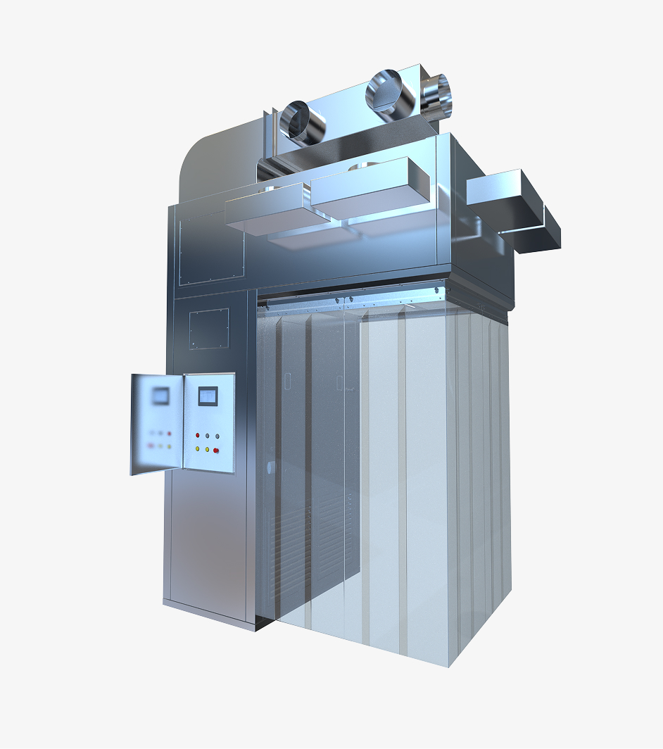
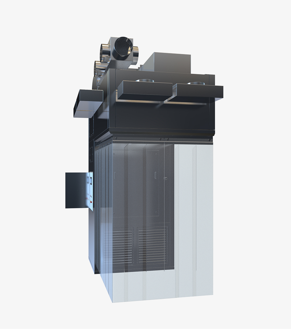
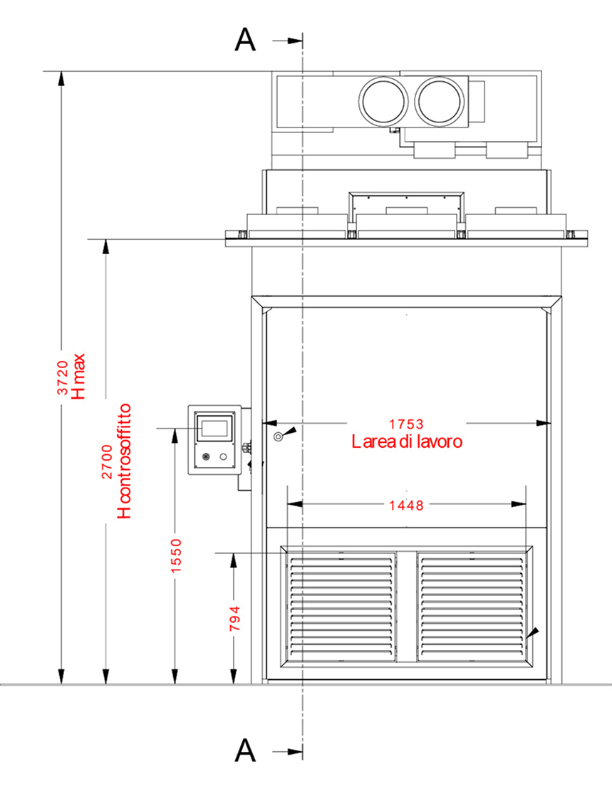
Central COLUMN
The central column is manufactured from sandwich panel with AISI 304 stainless steel sheet and Scotch Brite finish, with low surface roughness (Ra < 1.6 μm) and aluminum honeycomb interior.
All components are coplanar, with rounded edges and easy-to-sanitize surfaces. The rear casing houses the suction grids with G4 filters, the canisters with F9 filters, the HMI panel, complete with emergency stop buttons, pressure switches for monitoring the filters, and the electrical panel.
The instrumentation is accessed from the rear of the machine via the technical area, however the hood is also available in a compact version with complete frontal access, upon request. All joints are sealed with silicone to ensure airtightness and hygiene.
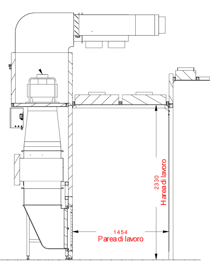
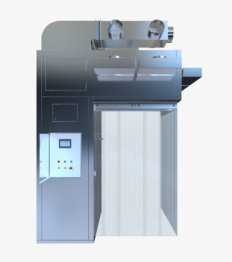
Upper Column
The upper casing is manufactured from AISI 304 stainless steel sheet sandwich wall panel and Scotch Brite exterior finish, with low surface roughness (< Ra 1.6 µm) and aluminum honeycomb filling.
All components are coplanar with rounded edges and easy to clean surfaces.
The upper casing houses the following elements:
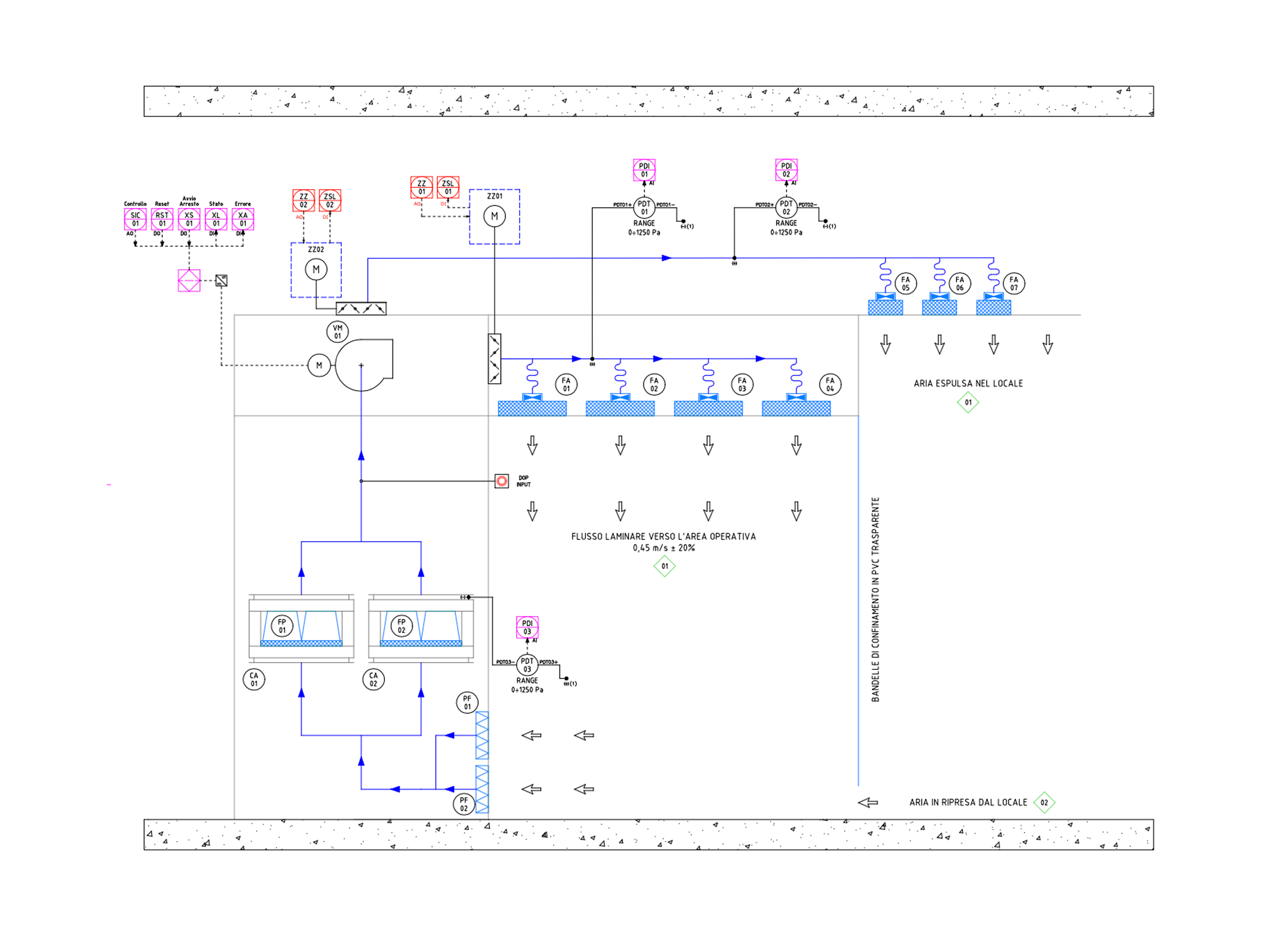
- The delivery fan that feeds the absolute filters and the expulsion filters
- The H14 absolute delivery filters (box type).
- The H14 absolute filters for the air expelled into the room (box type).
- The LED lamps for indoor lighting
The delivery filters, expulsion filters and LED lamps may be replaced from below. All joints are sealed with silicone to ensure airtightness.
The perimeter compartmentalization system, consisting of strips of flexible, transparent PVC, which, in the standard version, permits access to the working area via the front only, is mounted on the upper casing.
Control system
The system devices, equipment and components are controlled by PLC, which enables the operator to manage and monitor the hood system via the touch-screen operator interface.
The main functions of the control system are:
- Fan management
- Filter and fan alarm indications
- Graphical interface
The system features 2 operating modes:
- Local mode (standard): the machine can be started and stopped in manual mode by the operator.
- Remote mode (optional): the machine starts automatically when the department HVAC system is running.